
Electric Floor Heating Diagnostics: A Pro Field Guide to Troubleshooting Tile Floors
last updated october 12, 2026

In This Article
When a heated tile floor won’t heat or keeps tripping, the floor itself is rarely the problem. Most wasted time comes from checking things in the wrong order: replacing a thermostat that was fine, or opening tile when the real fix was a setting or a sensor wire. This guide walks through the diagnostic sequence our Tech Support team uses, so you can find the actual cause before anyone picks up a grout saw.
This guide is written for electricians and installers. If you’re a homeowner looking for a simpler overview, start with Troubleshooting the Most Common Floor-Heating Issues.
Key Takeaways
- Three ohm tests, not one: core-to-core plus both core-to-ground tests. Skipping the ground tests hides shorts.
- Megohmmeter for hidden faults: if the GFCI still trips after a clean meter test, test at 500 V and look for more than 10 megaohms.
- Sensor readings vary with temperature: only 0 ohms or OL (open line) proves the sensor has failed.
- GFCI trips: reset, check the breaker, check for a shared circuit, then ohm test — in that order.
- Floor heats but not enough: check the floor-limit setting before anything else.
- Install two sensors, connect one: a backup sensor turns a tile repair into a one-minute wire swap.
Download the PRO Field Checklist
Take this process to the job site. Our PRO Field Checklist: Electric Floor Heating Diagnostics & Troubleshooting puts the key tests and install checks on one printable page, with room to record your readings.
What Should You Check Before Replacing a Floor Heating Thermostat?
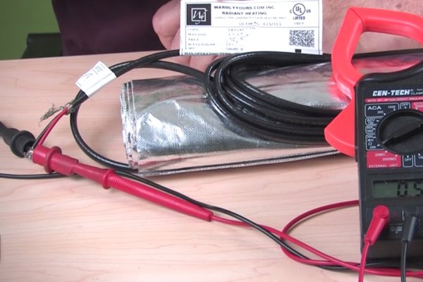
Start with complete heating-element tests rather than assuming the thermostat has failed. In this video, Anatoly, WarmlyYours Technical Support Manager, explains why one resistance reading isn’t enough, how a backup floor sensor can simplify troubleshooting, and why multiple heating mats should be tested individually. Watch this overview, then use the detailed diagnostic sections below.
Quick Diagnostic Table
| Symptom | Check first | Next step |
|---|---|---|
| GFCI red light on / thermostat tripping | Press reset on the thermostat | Breaker type and size, shared circuit, then the three ohm tests |
| Floor warms but won’t reach set temperature | Floor-limit / floor protection setting | Subfloor insulation, cable spacing, flooring with an attached pad |
| Thermostat reads 104–110°F on a cool floor | How many sensors are connected | Test sensor resistance; switch to the backup sensor |
| Half the floor is warm, half is cold | Thermal camera scan | Look for cable spaced wider than designed |
| Ohm or core-to-ground test fails | Call WarmlyYours tech support | Locate the fault with a Shortstop or the troubleshooting kit |
The Field Testing Toolkit
A few tools cover nearly every diagnostic call. Most electricians already own the first and last items on this list.
- Digital multimeter with a dial: skip analog needle meters and auto-ranging meters with no dial, which don’t always pick the right range. You want 200, 2k and 20k ohm settings.
- Megohmmeter: tests resistance at 250 or 500 V to find faults a 9-volt meter can’t see.
- Thermal imaging camera: shows warm and cold areas of the floor in seconds. Higher resolution makes hot spots easier to pinpoint. WarmlyYours rents them, and big-box stores do too.
- CircuitCheck continuity alarm: included with every indoor floor heating mat and cable. It sounds an alarm the moment the circuit is interrupted during installation.
- Voltage detector: the standard non-contact tester.
The Three Essential Ohm Tests
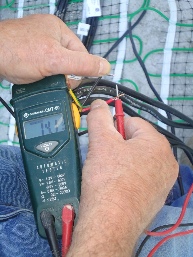
Resistance testing is always the first real test, because it tells you whether the heating element is intact. Many installers stop after the core-to-core reading matches the label. That reading only proves the wire is continuous. It says nothing about damage to the outer insulation or a short to ground.
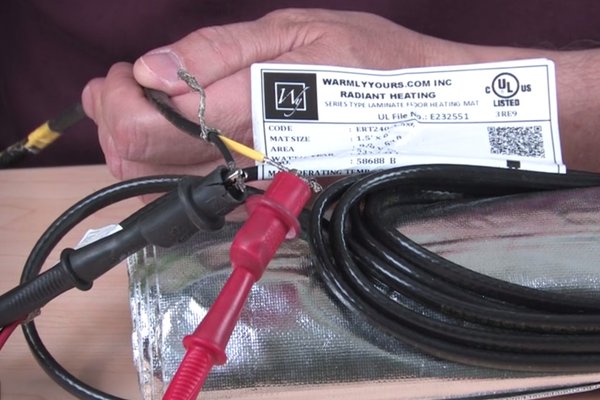
- Core-to-core: compare the reading with the resistance printed on the product’s UL label. Start on the 200-ohm range, which works for most installations. If the number flashes and disappears, the value is higher than that range — switch to 2k. For example, a short mat labeled 320 ohms might read 318 on the 2k setting, which is within range.
- Core-to-ground: test between one core wire and the ground. You should read nothing.
- Other core-to-ground: repeat from the other core wire to ground. Again, you should read nothing.
Any reading on either ground test points to a short. Record all three numbers every time.
Megohmmeter Testing for Hidden Faults
Sometimes all three ohm tests look clean, but the GFCI keeps tripping. A standard meter runs on a 9-volt battery, and it won’t detect a tiny gap between two conductors that aren’t quite touching. A megohmmeter charges to 500 V and sends that signal down the wire, so it can spark across a gap the multimeter misses.
Press and hold the test button to charge the meter, test, and read the result. More than 10 megaohms is a good reading. This test isn’t needed on every installation — it’s the next step when the standard tests pass and something is still tripping.
Use care at 500 volts
A megohmmeter test puts high voltage on the circuit. Make sure it is done carefully and correctly by a qualified person.
Floor Sensor Testing: Why There’s No Single “Right” Number
The floor sensor is a 10k-ohm thermistor on a 15′ lead. It runs next to the heating element’s lead wire, but not in the same conduit, so it doesn’t pick up a false reading. To test it, set your meter to the 20k scale.
Here’s the catch: a thermistor’s resistance changes with temperature. A sensor that reads about 10k ohms on the bench can drop to 8k, then 7k, within moments of someone holding the tip in a warm hand. A sensor delivered on a cold winter day may read high; the same sensor in a warm room may read low. In normal temperatures, expect somewhere between roughly 8k and 15k ohms.
So don’t condemn a sensor because it isn’t exactly 10k. The readings that do signal a failed sensor are 0 ohms (shorted) or OL (open line).
A 4-Step Flow for GFCI Trips
“My GFCI red light is on” is one of the most common calls we get. Work through these steps in order. The first three are easy and should happen before anyone schedules a service call.
- Reset the thermostat. Press the reset button and see whether that clears it.
- Check the breaker. Confirm it’s sized correctly, has the right voltage, and is not a GFCI breaker. WarmlyYours thermostats already have built-in GFCI protection, and two GFCI devices on one circuit can interfere with each other and cause nuisance trips. Use a regular breaker.
- Check for a shared circuit. Is the thermostat sharing a circuit with another thermostat, a fan, lights or a GFCI outlet? Try cycling the bathroom fan on and off repeatedly — sometimes it takes ten tries to trigger a trip. The fix is a dedicated circuit for the floor heating.
- Run the three ohm tests. If the readings are good, the thermostat is likely the problem. If they show a short or an open, contact us and we’ll help you repair or replace the product.
The GFCI test button tests the GFCI — not the system
Pressing “test” trips the unit on purpose, just like a kitchen outlet. If it resets and works, the GFCI is fine. If it won’t reset, the GFCI needs replacing. It tells you nothing about the heating element.
The System Tests Fine, But the Floor Isn’t Warm Enough
Start by asking whether the floor isn’t heating at all, or is heating to some temperature and stopping. If it’s warming, the system is running and something is limiting it.
Thermostat settings
- Floor limit / floor protection: laminate and vinyl usually call for a maximum of around 80–84°F. If a tile floor won’t climb past that, check whether it’s set for a protected floor covering. It’s a quick fix that doesn’t need an electrician.
- Manual mode for testing: put a programmable thermostat in manual mode before diagnostics, so a schedule doesn’t shut it off mid-test.
- Realistic expectations: a floor that won’t hit the thermostat’s 104°F maximum isn’t broken. Most people end up comfortable somewhere around 85–90°F in winter. Experiment with higher and lower settings before building a schedule.
Installation factors
- Heat loss into a slab: without insulation such as ThermalSheet over concrete, the slab can pull heat down and away from the floor.
- Cable spaced too wide: our recommended spacing for loose cable is 3″. When an installer finds extra square footage on install day and stretches the cable to 6″ to cover it, half the floor ends up cold. A thermal camera shows this in seconds.
- Heat footprint: heat spreads only about 1.5–2″ sideways from the element. If the mat stops short of the vanity, you get warm heels and cold toes.
- Wrong system for the depth: a thin mat is the wrong product under several inches of new concrete. Slab heating needs a different system.
- Padded flooring on top: laminate or LVP with an attached pad traps heat under it. Check with us before choosing flooring with pre-attached layers.
Installation photos help us enormously here. Often a picture of something else — a light switch, a doorway — shows the heating mat in the background and answers the question.
Backup Sensors: Free Insurance
Every WarmlyYours heating roll now ships with a floor sensor, marked with an orange sticker, and another sensor comes in the thermostat box — look under the insert at the bottom before throwing the box away. Install both, but connect only one. Place the probe tip about 6–8″ into the heated area.
- Put the two sensors in different parts of the room, so one accident can’t damage both.
- Avoid spots that will read warmer than the rest of the floor: under a hamper or wastebasket, in an afternoon sunbeam, or where the dog sleeps.
- Label the spare in the electrical box.
If the thermostat reads 110°F on a room-temperature floor at first startup, two sensors are probably connected at the same time. Remove the faceplate, check, and disconnect one.
Install Mistakes That Cause Future Failures
- Embed every cable: under tile, the heating element must be fully encapsulated in thinset mortar or self-leveling cement.
- Use a plastic trowel: sharp metal trowels can slice the thin outer jacket.
- Never cross, overlap or crowd the cable: spacing closer than 3″ creates a hot spot that can overheat until it fails.
- Treat the factory splice as heating element: space it like the rest of the cable and embed it. Never leave it in a wall cavity or open air.
- Don’t cross different substrates: where wood meets concrete — an addition, for example — use separate mats or cables so nothing can shear at the joint.
- Prep the subfloor: remove protruding screws, level uneven floors before the heat goes down, and prime before self-leveler if the bag calls for it.
- Keep the CircuitCheck connected through the whole installation, not just at the end.
Curing Time vs. Drying Time
Dry isn’t the same as cured. Mortar keeps bonding long after you can walk on it, and the bag tells you the cure time — 28 days is a general rule, but it may be 20 or 14 depending on the product. Rapid-set mortars get you to the next trade sooner, not to energizing the floor.
Heating an uncured floor can turn trapped moisture to steam and add thermal shock. If you need to confirm the system works in the meantime, run the ohm tests. You can also switch it on for just a couple of minutes to confirm it doesn’t trip and check amperage at the breaker. There’s no need to run it hot.
Three Real Case Files
Ground fault after grouting
The GFCI tripped right after grouting. The electrician ran the core-to-core test, got a reading that matched, and reported the system was fine. Without the core-to-ground tests, nobody saw the short. This is how jobs end up in a loop of replacement thermostats that trip exactly like the first one. Full testing — confirmed with a megohmmeter if needed — finds the fault on the first visit.
Sensor reading 104°F at startup
The thermostat showed 104°F immediately and the floor wouldn’t heat. The sensor tested at 3.2k ohms — about what you’d expect from a sensor sitting against a hot heating element. Switching to the backup sensor in the electrical box fixed it in about a minute, with no regrouting.
Shared circuit nuisance trips
“It only pulls 4 amps — can it share a circuit?” It might work for an hour, a month, or even years. We’ve seen units run five years before tripping, get replaced, and trip again, until a third call revealed the circuit was shared with everything else in the bathroom. A dedicated circuit avoids buying a thermostat that never failed.
Locating and Repairing a Fault
When testing confirms real damage, you rarely need to tear up the whole floor. Often it means lifting the one tile over the damaged section, repairing it, and resetting the tile.
- Shortstop: sends a signal down the cable and estimates the distance, in feet, to the short or break.
- Variable transformer (for shorts): apply a small voltage to heat the cable up to the short. On a thermal camera, the cable glows up to the fault and the rest of the floor stays cold.
- Hi-Pot (for open circuits): sends high-voltage pulses that spark at the break, creating a hot spot you can mark on the thermal image.
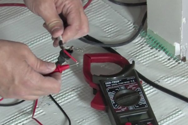
Both methods are in our complete troubleshooting rental kit. For a full walkthrough, see Heated Floor Troubleshooting and Repair: Find a Broken or Shorted Wire.
Prevention Checklist for Every Job
The best way to avoid a callback is a documented install. Our PRO Field Checklist: Electric Floor Heating Diagnostics & Troubleshooting puts these steps on one page.
- Test the product before installing and record the readings.
- Clean, check and level the subfloor.
- Keep the CircuitCheck connected throughout.
- Install two sensors and connect one.
- Fully embed the factory splice.
- Run final ohm and megohm tests and log them on the warranty card.
- Don’t energize until the mortar is fully cured.
Leave a copy of your readings with the client. If something goes wrong six months or a year later, those original numbers make diagnosis much faster.
Frequently Asked Questions
No. WarmlyYours floor heating thermostats have built-in GFCI protection, so indoor floor warming doesn’t need a GFCI breaker. Adding one can cause the two devices to interfere and produce nuisance trips. Use a regular, correctly sized breaker on a dedicated circuit.
It depends on temperature. The sensor is a 10k thermistor, and at normal room temperature it typically reads roughly 8k–15k ohms on the 20k scale. Warmth lowers the reading and cold raises it. Only 0 ohms or OL (open line) indicates a failed sensor.
Use one when the core-to-core and core-to-ground ohm tests look normal but the GFCI keeps tripping. A megohmmeter tests at 500 V and can find small insulation faults a standard multimeter misses. A reading above 10 megaohms is good. It isn’t required on every install.
Two floor sensors are most likely connected to the thermostat at the same time, which changes the resistance the thermostat sees. Remove the faceplate and disconnect one sensor, leaving the other in place as a labeled backup.
Need Help on Site?
Call our 24/7 ProTech line or email techsupport@warmlyyours.com. You can also reach your sales rep by chat or text.
Join the WarmlyYours PRO Program
Every diagnostic in this guide is easier with a team behind you. WarmlyYours PROs get contractor pricing, free SmartPlan layouts for every job, 24/7 installation support from our tech team, and access to certification and training. Register as a PRO today.
Have Questions About Your Project?
Our team of Radiant Experts is ready to help!
Related Articles
Troubleshooting the Most Common Floor-Heating Issues
Heated Floor Troubleshooting and Repair - Find a Broken or Shorted Wire
How to Use a Digital Ohmmeter

From Zero to Hero: Nail Damage Repair – Electric Floor Heating Fix
Stay Updated
Get the latest radiant heating news and tips delivered to your inbox.