

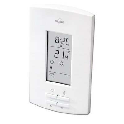
Aube Programmable Thermostats (TH111 series)
Main Products
Do you need support or specifications for a specific model? Identify your model below.
Support Questions
Showing 10 of 32 questions
To prevent any melting, ensure that the heating wire is at least 4” from the toilet wax ring.
When installing electric floor heating over a concrete slab, an insulating underlayment like ThermalSheet is highly recommended to ensure efficient operation, faster heating times and warmer floor temperatures.
Electric-resistance heating cables and systems have no polarity. This includes all current WarmlyYours heating elements.
The breaker and wire sizes are selected based on the total amperage of the WarmlyYours heating system connected to a single thermostat. This information is on the WarmlyYours heating system's installation plan, electrical plan, or UL label. Based on guidelines from the National Electrical Code: loads up to 16 Amps may utilize 12 gauge wire with a 20-Amp breaker, and loads up to 12 Amps - 14 gauge wire with a 15-Amp breaker. Local code and/or other factors may change these guidelines.
One thermostat can control multiple heating mats/cables as long as all the heating elements are using less than 15 amps:
TempZone™ will cover aprx. 120 sq. ft. for 120V systems and 240 sq. ft. for 240V systems on one thermostat.
Environ™ will cover aprx. 150 sq. ft. for 120V systems and 300 sq. ft. for 240V systems on one thermostat.
Slab Heat will cover aprx. 90 sq. ft. for 120V systems and 180 sq. ft. for 240V systems on one thermostat.
In theory, it is possible, if no other options are available. We do not recommend it, but If the thermostat is controlling the floor temperature with a floor sensor, then it can go on an exterior wall. It is important that the floor sensor gets located in an area of the floor not hit by sunshine.
If the thermostat will be controlling the air temperature with the built-in ambient sensor, then it should go on an interior wall.
WarmlyYours has recently begun including floor sensors with our heating elements to help ensure customers will have everything they need for optimal operation of their radiant heating systems.
The sensor included with your floor heating element can be installed with the heating system (the sensor is equally spaced between runs of the heating wire--see your install manual for more info). Installing this sensor with your floor heating control will enable energy efficient operation of the floor warming system based on the floor temperature instead of the ambient room temperature.
We generally recommend that you install a second, unconnected backup floor sensor alongside the primary one. In the very unlikely event that your first floor sensor is damaged, this install method will save you from having to pry up flooring to replace a floor sensor. You simply disconnect the damaged sensor from the thermostat and connect the backup sensor.
In addition to the floor sensor that was included with your heating element, our nSpiration Series thermostats also come with a floor sensor. If you purchase both a heating element and an nSpiration Series thermostat from WarmlyYours, you'll have a primary and a backup floor sensor for your system.
A GFCI/GFEP (Ground Fault Circuit Interrupter / Ground Fault Equipment Protection) works differently than a circuit breaker by specifically detecting a small imbalance in electrical current between the hot and neutral wires, which indicates a potential ground fault (like a person touching a live wire), and instantly shutting off the power to prevent shock, while a circuit breaker only trips when there's a significant overload in current flow on the circuit, like a short circuit or too many appliances plugged in.
The ground wire in the floor mat must be connected directly to the ground wire of the supply or to the house ground wire.
Relays can fail due to excessive current or voltage. When a relay is exposed to too much current, the contacts can burn out. High voltage can also damage the coil. Other reasons include mechanical wear and tear, dust or dirt buildup, and moisture. These factors can cause the relay to malfunction or stop working entirely. Regular maintenance and using the relay within its specified limits can help prevent failures.
If your thermostat is blank, the first thing to do is to test to see if voltage is present at the rear of the thermostat. If no power is reaching the thermostat, please inspect the circuit breaker powering the thermostat in the breaker panel, and verify that the breaker is a non-GFCI type. If it is a GFCI breaker, replace it with a non-GFCI breaker. If there is power entering the thermostat and it is blank, it will need to be replaced.
Turn off at the circuit breaker. Alternatively, the TH111 can be put in vacation mode by simultaneously pressing the sun and moon buttons. To program the vacation temperature, select the desired degree and press on the sun and moon buttons simultaneously (aprx. 3 seconds) until the suitcase icon is displayed.
Yes, the sensor wires may be trimmed. Most local code requirements call for 6“-7“ of extra wire from the gang box.
Resistance greater than this value may result in overheating or even total failure of the floor heating system. This may be caused by a crimping or other damage to the wire.
82°F - 85°F is the most common comfortable warm temperature of the floor.
Our thermostats are indoor rated. So long as they are kept within normal indoor humidity levels, they will continue to operate optimally. These thermostats are not rated to be installed in wet areas, steam rooms, or rooms with abnormal humidity levels or poor ventilation.
A digital meter with a 0-200 Ohms scale ( Ω ) to measure the heating wire's resistance, and a 20K scale to measure the sensor's resistance.
The flashing digits indicate that the actual (measured) floor temperature exceeds the thermostat temperature limit.
The temperature limit is set for either tile (104°F/40°C) or laminate (82°F/28°C) when the thermostat is first set up or re-configured.
For example: When the floor type (protection) is set to laminate, the limit defaults to 82°F/28°C. If the floor temperature goes above this - whether due to radiant floor heating or external heating sources, then the digits will flash and the heating is switched off.
Turning the temperature up or down will not affect the flashing digits. And leaving the thermostat alone with flashing digits does not harm the system.
Tip: To turn off the heated floor (ex. for months when it is not needed), on the outer edge of the thermostat, depress the lower right side button for 3-5 seconds. This will also turn it back on.
All thermostats are mandated at 42" height for handicap accessibility, most private residences are mounted at 52-60".
Please see this video on how to install a WarmlyYours nSpiration Series thermostat.
Yes, but the tear-out is the real risk. Scan the floor with thermal imaging before demo to map the existing hydronic tubing, and never fasten or drill into it. Keep the two systems on fully independent controls so they cannot fight each other, and do not place the electric floor sensor directly above a hydronic loop — the false-high reading will short-cycle the electric system. Call PRO technical support at 800-875-5285 to review the assembly before ordering.
No. Electric floor heating cable is listed for installation under floor coverings only, and the electrical code doesn’t allow it in walls: NEC 424.41(A) (2020 and earlier editions) prohibits heating cable in walls, and the 2023 NEC (424.48) allows it only for cable identified for wall installation, which ours is not. Running it vertically voids both the UL listing and the warranty. For warm towels and a little extra room heat, specify a heated towel rack, which is designed and listed for wall mounting.
Turn the power (circuit breaker typically) to the thermostat off for 5 minutes and then back on to reset the thermostat.
If there is power to the thermostat and it still doesn't appear to work, then the next step toward a solution is to take Ohm measurements of the floor heating system.
This is done with a digital multi-meter that can select a low 200 Ohm (Ω) scale. To conduct this test, turn off the circuit breaker. Remove the thermostat completely from the wall and disconnect the wires connected to the LOAD connections at the back of the thermostat. Disconnect the ground wires from the house ground, and do the test shown on the links below. If you are uncomfortable doing this test, contact a qualified electrician.
Please follow one of these guides based on the type of heating system installed:
For a quick overview of the testing process:
Here is a video showing how the test is done
Here is a video showing how to locate and identify the floor heating wires
If the system still does not function, contact +1 (800) 875-5285 WarmlyYours Technical Support and provide the Ohm measurements for further assistance.
Single Conductor vs. Twin Conductor Identification
- A single conductor floor heating system is a loop of one core wire, it starts at the thermostat and ends at the thermostat - this is the original method of manufacturing heating cable. Most single conductor floor heating systems have the same color cold lead wire connected to both load terminals/pigtails of the thermostat. Some early single conductor floor heating systems were produced with a white and a yellow cold lead wire.
- A twin conductor floor heating system terminates two core wires at the end, both wires start at the thermostat - this is the current method of manufacturing heating cable. Most twin conductor floor heating systems will have two different colored cold lead wires, and one of these is black. The other wire in a WarmlyYours floor heating system is either yellow (120V system) or red (240V system). A few early Environ systems had two black cold lead wires.
Note:
- Not all heating cables are wired directly to the thermostat. It may have been necessary during installation to terminate the heating cable in a junction box, and then run a separate (contractor-supplied) wire from the junction box to the thermostat.
- WarmlyYours single conductor cold leads were produced with a 13‘ length at the start of the loop, and a 26‘ length at the end. The 120V floor heating systems had a yellow and a white label attached to the cold leads, and the 240V floor heating systems had a red and a white label attached.
- If you have a single conductor floor heating system and notice that one cold lead is thicker or feels hotter than the other, please contact technical support at +1 (800) 875-5285
A variance of +/- 15% is acceptable.
For the same wattage and operating time, 120V and 240V electric floor heating use the same amount of energy and produce the same heat. A 240V system draws less current for the same wattage, which can accommodate a larger heated area on a suitable circuit. Choose the heating product and control voltage to match the supply, and have an electrician verify circuit capacity, wiring, and applicable code.
Resistance below this value may result in no heating or cold spots in the floor. This may be caused by exposure to moisture or other conductive material that penetrates the core insulation.
That is the sound the thermostat makes when the relay is either opened or closed to turn on or off the power to the floor heating elements. See this article for further information.
WarmlyYours controllers incorporate built-in Class A GFCI protection for all new floor heating systems. Class A GFCI provides personnel protection and trips when ground fault current exceeds 5 mA (milliamps). Class B GFCI protection is pretty much obsolete, but older systems may still require it. WarmlyYours controllers with built-in Class B GFCI provide equipment and circuit protection and operates when a fault to ground exceeds 15 mA.
For systems below 12 Amps, a 15 Amp, Non-GFI breaker is fine. For systems 12 to 16 Amps, a 20 Amp, non-GFI breaker is needed. Breaker sizes are noted on the installation plan that ships with many orders.
GFCI can fail for various reasons, such as wear and tear, moisture, corrosion, power surges, faulty wiring, or improper installation. Some of these causes can be prevented by regular inspection and maintenance, while others may require professional assistance. It is important to note that GFCI devices (ex. thermostat, breakers, outlets) should be tested regularly as these do wear out over time.
Temperature affects core resistance - lower temperatures decrease resistance and higher temperatures increase resistance. Another consideration is the test equipment, sometimes switching test units, adjusting the calibration, or allowing for the verified differential may be necessary.
A floor sensor measures floor temperature so a compatible thermostat can regulate comfort and enforce the flooring manufacturer’s temperature limit. Some thermostats, including nTrust 2.0, offer a regulator mode without a sensor, but that mode does not measure floor temperature. Use sensor-based temperature control whenever required by the flooring or heating-system instructions.
Documents
Publications
- Design Floor Plan Grid Wayfair (English)
- Floor Heating Products by Flooring Type and Subfloor (English)
Project Planners
- Calculating Project Dimensions (English)
- WarmlyYours Floor Heating Resale Value Fact Sheet (English)


