
Snow Melting Controls and Sensors: Getting Automatic Activation Right
last updated november 1, 2026

In This Article
Automatic snow melting starts with a sensor detecting moisture and a temperature low enough to meet the controller’s activation setting. The heating cable can be intact and the electrical design correct, yet a sheltered sensor or an unsuitable control setting can still leave the pavement covered. Choosing the control strategy, planning sensor locations, and checking operation before winter deserve as much attention as the heating layout.
This guide explains the decisions that matter for homeowners, facility managers, and installers. Electrical installation, live measurements, and fault diagnosis belong with a qualified electrician using the exact controller and sensor instructions.
Quick Facts: snow melting controls and sensors
- What triggers automatic snow melting? Moisture and a temperature that meets the controller’s cold-weather threshold must both be present for this sensing logic to call for heat.
- Is 38°F the setting for every controller? No. The SCA-DUAL uses 38°F (3.3°C); the SCE-120 has an adjustable factory setting of 37.4°F (3°C). Use the installed model’s instructions.
- Which sensor should you choose? Aerial sensors detect conditions at their mounting location; in-slab sensors monitor the pavement. Compatibility and placement matter more than a universal preference.
- How long should after-run last? There is no universal duration. Start with the controller’s documented settings and review actual clearing performance.
- When should you check the system? Before freezing weather. A heat indicator alone does not confirm that heating circuits draw the expected current; electrical testing belongs with a qualified professional.
Before getting into controller selection, watch this short deep dive on sensor placement, wiring, and preseason checks. It connects the control settings discussed below with the practical questions contractors face on a service visit.
The video puts those installation and service checks in context. To plan them well, start with the activation rule itself: what conditions must the sensor detect before the controller calls for heat?
How automatic snow melting activation works
Think of automatic activation as an AND rule: the sensor must detect moisture, and the measured temperature must satisfy the controller’s cold-weather threshold. Cold, dry weather alone does not call for snow melting through this sensing logic. Moisture above the threshold does not either.
38°F is a common threshold, not a universal specification. The SCA-DUAL uses 38°F (3.3°C); the SCE-120 has an adjustable factory setting of 37.4°F (3°C). Follow the instructions for the installed model rather than treating 32°F or 38°F as a setting for every system.
Cold rain can therefore activate a system when both conditions are met. Also distinguish what is being measured: an aerial sensor detects conditions at its mounting location, while a pavement sensor detects conditions at the heated surface. Neither location tells the whole story about every part of a driveway.
Choose a control strategy before choosing a controller
Manual timers and remote switches
A manual timer can suit an area used on a predictable schedule, provided someone will start the system when needed. A Wi-Fi switch adds remote access, but remote switching alone is still manual control. Consider what happens when snow starts overnight or while the property is unattended.
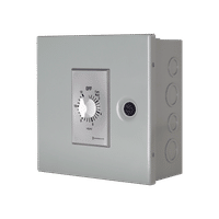
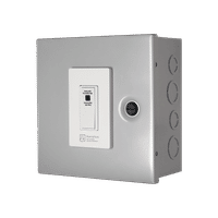
Do not plan around waiting for deep accumulation before switching on. Starting as conditions develop gives the system an opportunity to respond before a substantial snow layer builds up.
Automatic sensing
Automatic controls respond without someone watching the forecast and operating a switch. The practical choice depends on the heating load, sensor compatibility, number of sensing locations, mounting environment, and any required pavement-temperature limit.
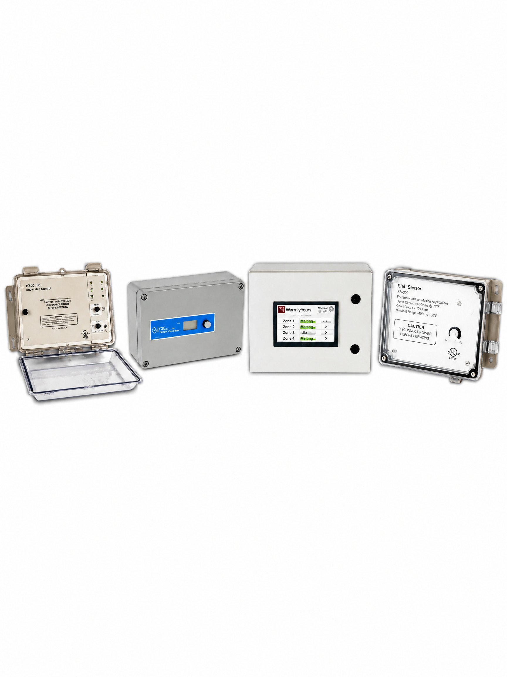
| Controller | Rating or configuration | Sensor and selection qualifications |
|---|---|---|
| SCV-DUAL | 16 A maximum rating | Integrates sensing and control in one unit. |
| SCA-DUAL | 30 A maximum rating | Supports two compatible sensors total—not two additional sensors. |
| SCE-120 | Two independent electric-heating zones in its documented configurations | Sensor selection and wiring depend on the application. Do not treat this simply as a two-sensor controller. |
| SCP-120 | 24 A maximum rating | Supports up to six compatible precipitation sensors and includes a high-limit probe. Its maximum rating is lower than the SCA-DUAL’s; a more capable control interface does not necessarily mean a higher directly switched load. |

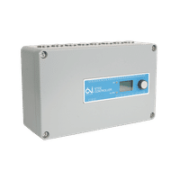
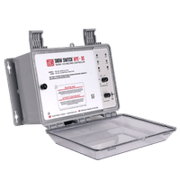
These are selection checkpoints, not a wiring or circuit-sizing chart. The electrician must confirm supply requirements, permissible heating loads, protection, and any external contactors against the project documents.
Sequential zoning for limited electrical capacity
The ZoneBraker SC-MZ-TOUCH can control up to four zones through contactors. Its Multi-Zone Auto mode operates zones sequentially, while Single-Zone Auto is intended for configurations with adequate power to operate zones simultaneously.
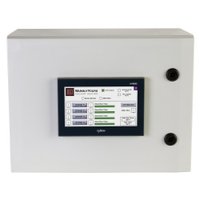
Sequential operation manages peak electrical demand; it does not make the entire driveway heat at once on a smaller supply, nor does it guarantee lower total energy use. Prioritize critical areas and discuss the performance trade-offs during design. For background, read how multi-zone snow melting control works.
Aerial sensors versus in-slab sensors
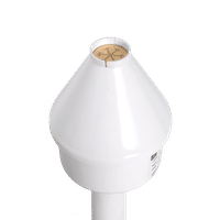
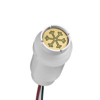
Aerial sensors are useful for detecting falling precipitation and can be accessible for inspection and cleaning. Their limitation is straightforward: snow that never reaches the sensing surface cannot trigger that sensor.
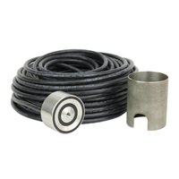
In-slab sensors monitor conditions at the pavement. They can be useful where moisture reaches the surface without fresh snowfall, such as entrances, ramps, or loading areas. The selected sensor must be compatible with the controller; aerial, pavement, and temperature-limit probes are not interchangeable.
| Sensor type | What it monitors | Main placement consideration |
|---|---|---|
| Aerial | Conditions at the mounting location, including falling precipitation | Precipitation must reach the sensing surface. Keep it accessible for inspection and follow the exact model’s mounting instructions. |
| In-slab | Conditions at the pavement, including surface moisture without fresh snowfall | Plan rough-in before paving. Follow the selected sensor’s instructions for housing, conduit, sensing-face position, and service access. |
Compatibility comes first: aerial sensors, pavement sensors, and temperature-limit probes are not interchangeable. Neither sensing location represents every part of a driveway.
Give aerial sensors exposure and service access
- Choose an open location where precipitation can reach the sensing grid.
- Avoid overhangs, trees, roof runoff, and warm exhaust that can distort what the sensor detects.
- Consider wind patterns and snow accumulation around buildings.
- Keep the sensor accessible for safe cleaning and inspection.
- Follow the exact sensor’s mounting instructions for height and orientation. Do not apply a generic tilt recommendation to every sensor design.
Plan pavement sensor rough-in before paving
Locate the sensor within the heated area, midway between heating runs, and install its sensing face flush with the finished surface as directed by its manual. Use the specified housing and conduit arrangement so the sensor can be serviced rather than permanently burying the sensing head.
The location should represent the conditions the system needs to detect, without creating an artificial puddle or exposing the sensor to avoidable damage and contamination. Tire-track placement needs project-specific review: traffic may deliver the moisture of interest, but road salt, packed debris, and mechanical loading also matter. Confirm the final location with the sensor instructions and design team.
Use after-run time to address what remains after snowfall
After-run, also called hold-on time, keeps heating active after the precipitation signal ends. An aerial sensor can dry before the pavement has finished clearing, so an immediate shutdown may leave residual slush or meltwater.
There is no single correct duration for every slab and storm. Begin with the controller’s documented settings, then observe actual performance. If the system stops with slush remaining, review whether more after-run is appropriate. If the heated area is already clear and dry but heating continues for an unnecessary period, review whether it can be reduced.
Drainage, shade, wind, temperature, and snowfall affect the result. More runtime cannot correct inadequate drainage, insufficient heating output, or a sensor that never called for heat. Nor does a timer guarantee that every wet area will remain ice-free.
Relays expand switching capacity—not available power
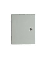
A controller may operate external contactors or relay panels when the project exceeds its directly switched load or uses a configuration that requires them. The controller provides the operating command; the switching equipment handles the heating circuits.
A relay panel does not add electrical service capacity. Future expansion still requires review of the supply, protection, control interfaces, sensor coverage, and revised heating design. Gather those details using our snow melting project planning checklist.
This relay panel is one example; panel selection and sizing must be confirmed for the specific project.
Preseason checklist: inspect, confirm, test, and document
Arrange a check before freezing weather rather than waiting for the first storm. Accessible sensors deserve attention even when the buried heating elements require little routine maintenance.
Before the service visit: inspect and identify
- Inspect accessible areas safely. Check sensor exposure, debris, visible damage, and changes to nearby landscaping or drainage.
- Identify the equipment. Record the exact controller and sensor models and keep their diagrams with the project records.
With a qualified professional: confirm settings and verify operation
- Confirm model-specific settings. Review automatic operating mode, after-run, and required temperature-limit inputs using the installed equipment’s instructions.
- Verify the complete heating response. Have a qualified professional use the model-specific test procedure to establish a call for heat, confirm switching, and measure heating-circuit current against the design.
After the check: keep a usable record
- Document the results. Record readings, settings, observed faults, and any corrective work.
An illuminated heat indicator alone does not prove the heating circuits are drawing the expected current. Conversely, a single successful test does not guarantee performance in every storm.
Some sensor procedures simulate cold and moisture, but the test method must match the installed sensor. Do not submerge a weather-resistant sensor, improvise with an inverted aerosol can, or perform live electrical measurements without the appropriate qualifications. Never bypass a required high-limit sensor to restore normal operation; investigate the fault with technical support.
When the system does not behave as expected
- No activation during snowfall: first inspect whether precipitation is reaching the sensor. Record the controller indicators and any fault code before requesting help.
- Heat indication but little melting: have the electrician verify actual heating current and circuit operation; an indicator is not a complete diagnosis.
- Heating continues after the storm: check whether after-run is active and whether moisture is still reaching the sensor.
- Repeated faults or a missing limit probe: use the exact model’s troubleshooting instructions. Do not assume every flashing light has the same meaning.
Resources for the project file
The PRO Technical Field Guide for Snow Melting Controls and Sensors covers activation, placement, hold-on time, and commissioning. Use it alongside—not instead of—the current instructions for the exact installed equipment. General placement and test examples are not universal installation directions.
Plan the activation strategy with the heating layout
Bring WarmlyYours your dimensions, surface type, available electrical capacity, and operating priorities. Include proposed sensor locations and any future expansion so the design can account for the whole system.
Have Questions About Your Project?
Our team of Radiant Experts is ready to help!
Related Articles
Stay Updated
Get the latest radiant heating news and tips delivered to your inbox.