
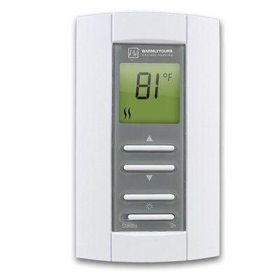
Thermostat EasyStat™ Non Programmable 240V with GFCI 5mA
This product is discontinued.
This support page provides publications, manuals, specifications, videos, support articles, and common support questions
Support Questions
Showing 10 of 21 questions
The breaker and wire sizes are selected based on the total amperage of the WarmlyYours heating system connected to a single thermostat. This information is on the WarmlyYours heating system's installation plan, electrical plan, or UL label. Based on guidelines from the National Electrical Code: loads up to 16 Amps may utilize 12 gauge wire with a 20-Amp breaker, and loads up to 12 Amps - 14 gauge wire with a 15-Amp breaker. Local code and/or other factors may change these guidelines.
One thermostat can control multiple heating mats/cables as long as all the heating elements are using less than 15 amps:
TempZone™ will cover aprx. 120 sq. ft. for 120V systems and 240 sq. ft. for 240V systems on one thermostat.
Environ™ will cover aprx. 150 sq. ft. for 120V systems and 300 sq. ft. for 240V systems on one thermostat.
Slab Heat will cover aprx. 90 sq. ft. for 120V systems and 180 sq. ft. for 240V systems on one thermostat.
In theory, it is possible, if no other options are available. We do not recommend it, but If the thermostat is controlling the floor temperature with a floor sensor, then it can go on an exterior wall. It is important that the floor sensor gets located in an area of the floor not hit by sunshine.
If the thermostat will be controlling the air temperature with the built-in ambient sensor, then it should go on an interior wall.
A GFCI/GFEP (Ground Fault Circuit Interrupter / Ground Fault Equipment Protection) works differently than a circuit breaker by specifically detecting a small imbalance in electrical current between the hot and neutral wires, which indicates a potential ground fault (like a person touching a live wire), and instantly shutting off the power to prevent shock, while a circuit breaker only trips when there's a significant overload in current flow on the circuit, like a short circuit or too many appliances plugged in.
Relays can fail due to excessive current or voltage. When a relay is exposed to too much current, the contacts can burn out. High voltage can also damage the coil. Other reasons include mechanical wear and tear, dust or dirt buildup, and moisture. These factors can cause the relay to malfunction or stop working entirely. Regular maintenance and using the relay within its specified limits can help prevent failures.
If your thermostat is blank, the first thing to do is to test to see if voltage is present at the rear of the thermostat. If no power is reaching the thermostat, please inspect the circuit breaker powering the thermostat in the breaker panel, and verify that the breaker is a non-GFCI type. If it is a GFCI breaker, replace it with a non-GFCI breaker. If there is power entering the thermostat and it is blank, it will need to be replaced.
The flashing digits indicate that the actual (measured) floor temperature exceeds the thermostat temperature limit.
The temperature limit is set for either tile (104°F/40°C) or laminate (82°F/28°C) when the thermostat is first set up or re-configured.
For example: When the floor type (protection) is set to laminate, the limit defaults to 82°F/28°C. If the floor temperature goes above this - whether due to radiant floor heating or external heating sources, then the digits will flash and the heating is switched off.
Turning the temperature up or down will not affect the flashing digits. And leaving the thermostat alone with flashing digits does not harm the system.
Tip: To turn off the heated floor (ex. for months when it is not needed), on the outer edge of the thermostat, depress the lower right side button for 3-5 seconds. This will also turn it back on.
Turn the power (circuit breaker typically) to the thermostat off for 5 minutes and then back on to reset the thermostat.
If there is power to the thermostat and it still doesn't appear to work, then the next step toward a solution is to take Ohm measurements of the floor heating system.
This is done with a digital multi-meter that can select a low 200 Ohm (Ω) scale. To conduct this test, turn off the circuit breaker. Remove the thermostat completely from the wall and disconnect the wires connected to the LOAD connections at the back of the thermostat. Disconnect the ground wires from the house ground, and do the test shown on the links below. If you are uncomfortable doing this test, contact a qualified electrician.
Please follow one of these guides based on the type of heating system installed:
For a quick overview of the testing process:
Here is a video showing how the test is done
Here is a video showing how to locate and identify the floor heating wires
If the system still does not function, contact +1 (800) 875-5285 WarmlyYours Technical Support and provide the Ohm measurements for further assistance.
WarmlyYours controllers incorporate built-in Class A GFCI protection for all new floor heating systems. Class A GFCI provides personnel protection and trips when ground fault current exceeds 5 mA (milliamps). Class B GFCI protection is pretty much obsolete, but older systems may still require it. WarmlyYours controllers with built-in Class B GFCI provide equipment and circuit protection and operates when a fault to ground exceeds 15 mA.
GFCI can fail for various reasons, such as wear and tear, moisture, corrosion, power surges, faulty wiring, or improper installation. Some of these causes can be prevented by regular inspection and maintenance, while others may require professional assistance. It is important to note that GFCI devices (ex. thermostat, breakers, outlets) should be tested regularly as these do wear out over time.
A floor sensor measures floor temperature so a compatible thermostat can regulate comfort and enforce the flooring manufacturer’s temperature limit. Some thermostats, including nTrust 2.0, offer a regulator mode without a sensor, but that mode does not measure floor temperature. Use sensor-based temperature control whenever required by the flooring or heating-system instructions.
Documents
Operation Manuals
Wiring Diagrams
- SmartStat™, EasyStat™, Comfort Regulator, Power Module Wiring Diagram with TempZone™ Twin Conductor or Environ™ (120V or 240V) (English)
- SmartStat TH115 to TempZone Flex Wiring Diagram (English)
- SmartStat™, EasyStat™ Wiring Diagram with Multiple Environ™ using a Junction Box (English)
- SmartStat™, EasyStat™, Comfort Regulator, Power Module Wiring Diagram with Environ™ 120V or 240V Flat Lead (English)
- TempZone™ Custom & Standard Mat Wiring Diagram (English)
- WIRING DIAGRAM 120V & 240V Heating Products with PB112D-GA (English)
- Wiring Diagram for TempZone™ Cut & Turn Single Conductor (Multiple rolls) 120V & 240V with SmartStat™, EasyStat™ and Comfort Regulator (English)
- Wiring Diagram for TempZone™ Cut & Turn Twin Conductor (Multiple Rolls) 120V & 240V with SmartStat™, EasyStat™, Comfort Regulator and Power Modules (English)
- Wiring Diagram for TempZone™ Cut & Turn Twin Conductor 120V & 240V with SmartStat™ and EasyStat™ (English)
- Wiring Diagram for TempZone™ Cut & Turn Twin Conductor 120V & 240V with SmartStat™, EasyStat™ and Comfort Regulator (English)
Sell Sheets
Technical Information
Installation
Specifications
Electrical
| Connection | Double pole, 4 wires, line 1 & line 2 |
| Connection Method | Hardwired |
| Maximum Load (Resistive Only) | 1800 W - 120 V, 15 A |
| Voltage | 240 V |
| Watts | 1500 W |
Product Dimensions
| Depth | 2″ |
| Installed Depth | 0.75″ |
| Length | 3.5″ |
| Weight | 1 lbs |
| Width | 2.5″ |
Identifiers
| Ground Fault Protection (GFCI) | Class A, 5 mA |
| SKU | TH114-AF-240GA |
| UPC (GTIN-12) | 881308020644 |
Thermostat
| Has Floor Sensor | y |
Videos
Articles
- Checking heating current with an EasyStat TH114 thermostat
- Choosing wood flooring for electric radiant heating
- Electric radiant heat under LVT, vinyl and resilient flooring
- ETI Floorstat FWT-3: operation and replacement considerations
- Extending floor-heater cold leads and sensor wiring
- Finding LVT products compatible with electric floor heating
- Floor heating and implanted pacemakers: checking compatibility
- FLOR carpet tiles over radiant floor heating
- How to reduce winter gaps in wood flooring
- Resistance values for the Resideo/Honeywell Home AC112-01 floor sensor
- TH115 or TH114 thermostat has a blank display
- Why a relay thermostat clicks when heating switches
