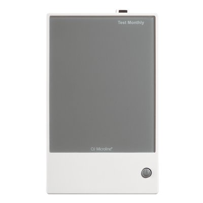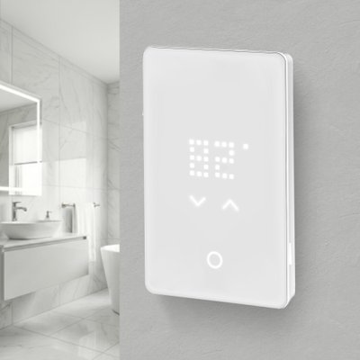
nTrust 2.0 Touch Nonprogrammable Thermostat (UTN5-4999)
Part Number: UTN5-4999
This support page provides publications, manuals, specifications, videos, support articles, and common support questions
This support page provides publications, manuals, specifications, videos, support articles, and common support questions
Jump to
Support Questions
Showing 10 of 19 questions
The breaker and wire sizes are selected based on the total amperage of the WarmlyYours heating system connected to a single thermostat. This information is on the WarmlyYours heating system's installation plan, electrical plan, or UL label. Based on guidelines from the National Electrical Code: loads up to 16 Amps may utilize 12 gauge wire with a 20-Amp breaker, and loads up to 12 Amps - 14 gauge wire with a 15-Amp breaker. Local code and/or other factors may change these guidelines.
In theory, it is possible, if no other options are available. We do not recommend it, but If the thermostat is controlling the floor temperature with a floor sensor, then it can go on an exterior wall. It is important that the floor sensor gets located in an area of the floor not hit by sunshine.
If the thermostat will be controlling the air temperature with the built-in ambient sensor, then it should go on an interior wall.
A GFCI/GFEP (Ground Fault Circuit Interrupter / Ground Fault Equipment Protection) works differently than a circuit breaker by specifically detecting a small imbalance in electrical current between the hot and neutral wires, which indicates a potential ground fault (like a person touching a live wire), and instantly shutting off the power to prevent shock, while a circuit breaker only trips when there's a significant overload in current flow on the circuit, like a short circuit or too many appliances plugged in.
Relays can fail due to excessive current or voltage. When a relay is exposed to too much current, the contacts can burn out. High voltage can also damage the coil. Other reasons include mechanical wear and tear, dust or dirt buildup, and moisture. These factors can cause the relay to malfunction or stop working entirely. Regular maintenance and using the relay within its specified limits can help prevent failures.
No, a circuit breaker will NOT protect against a power surge; a circuit breakers primary function is to protect against excessive current flow (overload), while a surge protector is specifically designed to handle voltage spikes, which are what power surges are considered to be.
The flashing digits indicate that the actual (measured) floor temperature exceeds the thermostat temperature limit.
The temperature limit is set for either tile (104°F/40°C) or laminate (82°F/28°C) when the thermostat is first set up or re-configured.
For example: When the floor type (protection) is set to laminate, the limit defaults to 82°F/28°C. If the floor temperature goes above this - whether due to radiant floor heating or external heating sources, then the digits will flash and the heating is switched off.
Turning the temperature up or down will not affect the flashing digits. And leaving the thermostat alone with flashing digits does not harm the system.
Tip: To turn off the heated floor (ex. for months when it is not needed), on the outer edge of the thermostat, depress the lower right side button for 3-5 seconds. This will also turn it back on.
Yes. The floor never free-runs — the thermostat’s floor sensor governs output, and you set a maximum floor temperature limit in the thermostat itself. Most heated tile bathroom floors are set between 80°F and 85°F. Set that limit during commissioning and record it on the handoff sheet so the homeowner does not raise it past the flooring manufacturer’s rated maximum.
Yes, but the tear-out is the real risk. Scan the floor with thermal imaging before demo to map the existing hydronic tubing, and never fasten or drill into it. Keep the two systems on fully independent controls so they cannot fight each other, and do not place the electric floor sensor directly above a hydronic loop — the false-high reading will short-cycle the electric system. Call PRO technical support at 800-875-5285 to review the assembly before ordering.
No. Electric floor heating cable is listed for installation under floor coverings only, and NEC 424.38(A) does not permit heating cable to be installed in walls. Running it vertically voids both the UL listing and the warranty. For warm towels and a little extra room heat, specify a heated towel rack, which is designed and listed for wall mounting.
No separate GFCI breaker is required — every WarmlyYours thermostat has a built-in Class A (5mA) GFCI. Stacking a GFCI breaker on top of it is one of the most common causes of nuisance tripping. Run a dedicated breaker sized to the load at 80% continuous duty: a 15A circuit carries up to 1,440W at 120V, a 20A circuit up to 1,920W. Loads beyond the thermostat’s 15A rating need a power module or relay.
To completely power off the thermostat, turn off the circuit breaker controlling the thermostat.
Alternatively, put the thermostat into Standby/Frost Protection mode by pressing the lower right button once. A Standby icon will show for a few seconds before it fades out. The thermostat is now in standby. To exit standby, press the lower right button for a moment.
Error code “E2” means the floor sensor is defective, damaged or not connected. Check the connections, and replace the sensor if needed. Test the sensor with a digital multimeter on the 20k scale. Because the sensor is a thermistor, its resistance changes with temperature: it typically reads about 8kΩ–15kΩ at normal room temperature, lower when warm and higher when cold. A reading of 0 ohms or OL (open line) indicates a failed sensor. Only one floor sensor can be connected to a thermostat.
The best home features for cold climates include a simple gable roof to shed snow, covered entrances for protection, airtight triple-pane windows to prevent heat loss, and radiant heating systems. These features work together to maintain interior warmth, reduce energy bills by up to 25%, and ensure structural safety during harsh winters.
The nTrust 2.0 can operate in 'Regulator mode', which does not require a floor sensor in this mode.
'Sensorless mode' is a 'regulator mode' in the nTrust 2.0 (UTN5-4999) thermostat. This allows selecting a heating percentage without use of any temperature sensor (aka 'regulator mode'). This mode of operation is selectable only during the initial setup wizard.
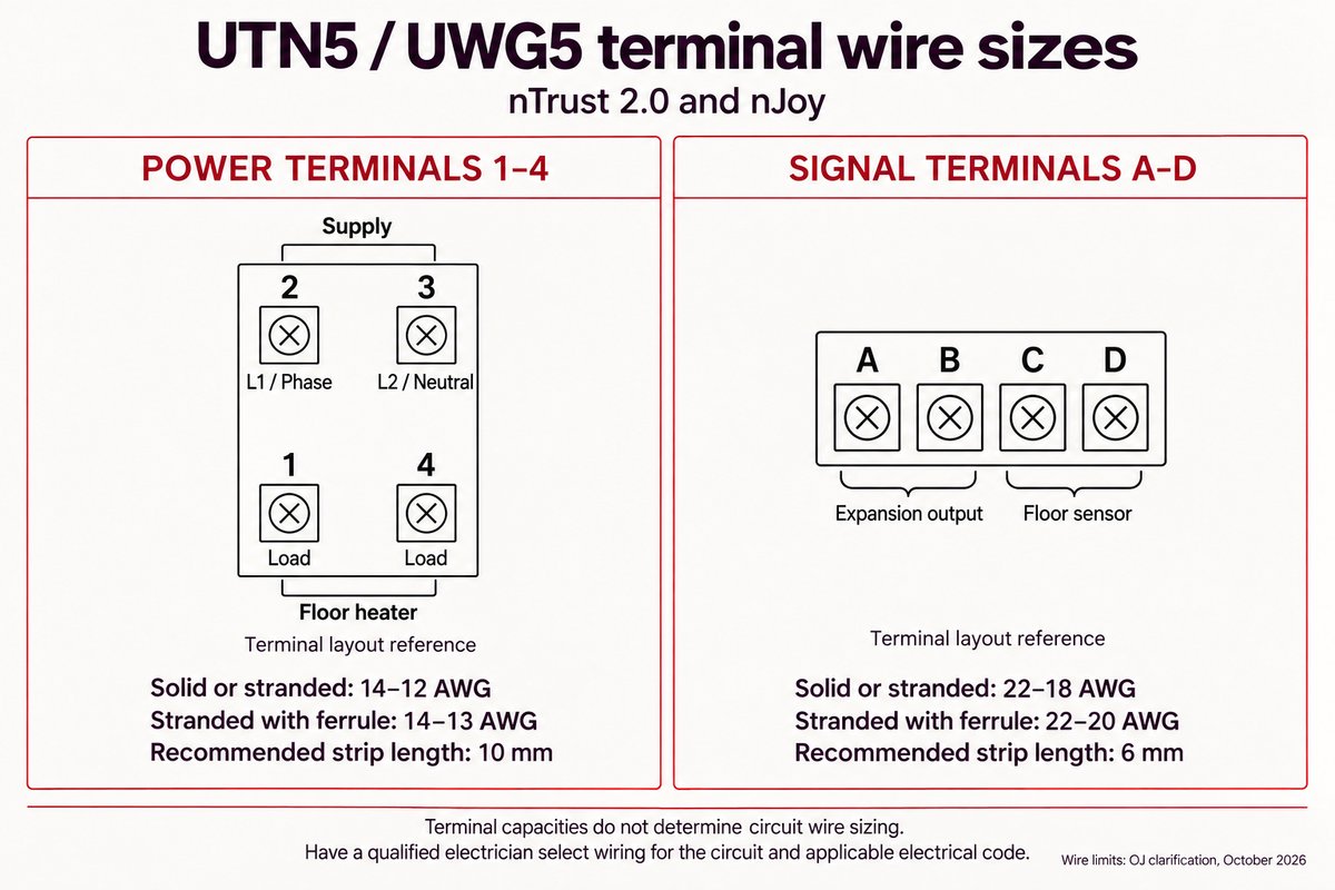
For nTrust 2.0 (UTN5) and nJoy (UWG5), power and signal terminals have different wire limits:
- Power terminals (1–4): 14–12 AWG solid or stranded wire; 14–13 AWG stranded wire with ferrules. Recommended strip length: 10 mm.
- Signal terminals (A–D): 22–18 AWG solid or stranded wire; 22–20 AWG stranded wire with ferrules. Recommended strip length: 6 mm.
These are terminal capacities, not circuit-sizing instructions. Have a qualified electrician select wiring for the circuit and applicable electrical code.
GFCI can fail for various reasons, such as wear and tear, moisture, corrosion, power surges, faulty wiring, or improper installation. Some of these causes can be prevented by regular inspection and maintenance, while others may require professional assistance. It is important to note that GFCI devices (ex. thermostat, breakers, outlets) should be tested regularly as these do wear out over time.
A floor sensor measures floor temperature so a compatible thermostat can regulate comfort and enforce the flooring manufacturer’s temperature limit. Some thermostats, including nTrust 2.0, offer a regulator mode without a sensor, but that mode does not measure floor temperature. Use sensor-based temperature control whenever required by the flooring or heating-system instructions.
Documents
Technical Information
Sell Sheets
- Radiant Heating Controls Comparison Chart USA (English)
- nTrust 2.0 UNT5 Touch Nonprogrammable Thermostat Sell Sheet USA (English)
Installation
- Setting Up the nTrust 2.0 UTN5-4999 (English)
- nTrust 2.0 UTN5 Touch Nonprogrammable Thermostat Startup Guide (English, French)
- nTrust 2.0 UTN5 Touch Nonprogrammable Thermostat Startup Guide (English, Spanish)
Wiring Diagrams
Operation Manuals
Specifications
Warranty / Certifications
| Approvals | cULus listed |
| Ingress Protection (IPxx) Rating | IP20 |
| Warranty | Limited 3-year warranty and lifetime technical support |
Electrical
Appearance
| Color | White Acrylic |
| Display | LED Light Through |
Product Dimensions
| Depth | 1.73″ |
| Installed Depth | 0.46″ |
| Length | 4.98″ |
| Weight | 0.6 lbs |
| Width | 3.09″ |
Thermostat
| Floor Sensor Compatibility | 10k ohms or 12k ohms |
| Includes Floor Sensor | 10k ohms, 15′ lead |
| Maximum Ambient Temperature Setting | 77 °F |
| Maximum Floor Temperature Setting | 104 °F |
| Minimum Ambient Temperature Setting | 32 °F |
| Minimum Floor Temperature Setting | 41 °F |
Identifiers
| SKU | UTN5-4999 |
| UPC (GTIN-12) | 881308080426 |
Videos
Articles
Related Items
Do you need support or specifications for a specific model? Identify your model below.